There are bolted connections throughout many aerial adventure operations, and it’s important to understand the mechanics involved. Tightening a bolt too much or too little—that is, applying too much or too little torque—significantly affects how well the bolt will do its job, and for how long it will do it.
Nuts and bolts can be manufactured and specified to various standards and measures: metric (made to the ISO 898-1 standard) and ASTM structural fasteners, for example. This discussion focuses on SAE J429 fasteners, i.e., the familiar Grade 2, 5 and 8 fasteners, measured in inches, but the principles are the same for all.
Bolted Connections, Clamping Force and Friction
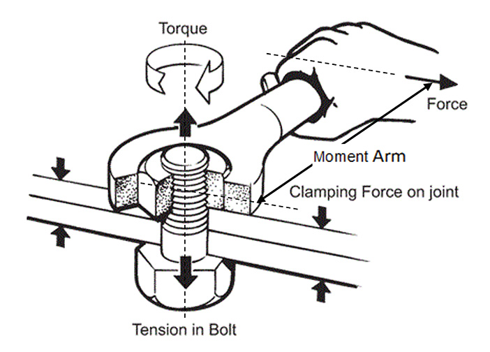
Torqueing a nut stretches a bolt, creating a clamping force so that friction can hold a bolted joint together. The bolt acts like a very stiff spring. Friction, created by the clamping force that results from tightening a nut on a bolt, holds the joint together. The thread on a nut and a bolt is an inclined plane, so rotating the nut moves the nut up the plane. That stretches the bolt and creates the clamping force. This also increases the friction between the parts being connected, and that friction holds the parts together.
Torque
Torque is a measure of the effort it takes to twist something, like a nut or bolt or bottlecap. Numerically, it is the product of a force and the distance (moment arm) it acts through to create the twist (see Figure 2, below). For a given force, the longer the moment arm, the greater the torque.

Figure 2: Torque and clamping force (ex. Smartbolts).
Foot-pounds (ft-lb) are the commonly-used units to measure torque, but inch-pounds (in-lb) and newton-meters (Nm) are also used. Converting from one to another is only a matter of multiplying by conversion factors.
Consider these examples:
• A one hundred pound force (100 lb.) acting to twist a nut from the end of a one foot (1 ft.) wrench applies a torque of one hundred foot-pounds: 100 lb. x 1 ft. = 100 ft-lb.
• Thirty-six pounds applied to a nut with a four-inch-long wrench produces a torque of 144 inch-pounds (36 lb. x 4 in. = 144 in-lb). To convert this figure to ft-lb, divide the inches by 12. This can be expressed as 36 lb. x 4/12 ft. = 12 ft-lb.
Steel Bolts
Steel has an elastic range in which it acts like a spring. In this range, the steel returns to its original shape when a load is removed. The more a bolt is stretched, the harder it pulls back to return to its original length. This spring action is what holds connected parts together.
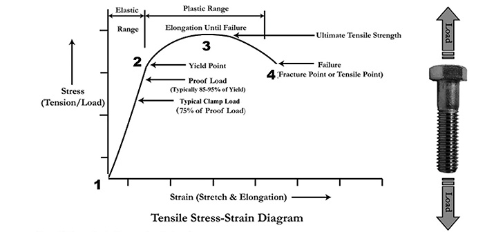
For steel in general, this spring action is described with a stress-strain diagram (Figure 3, below). The essential points are these:
Strain (stretch). The horizontal axis is a measure of stretch. It is the elongation divided by the original length.
Stress (load). The vertical axis is stress, which is a measure of load. Its units are pounds per square inch (psi), like pressure.
Tensile stress. For a bolt in tension, its tensile stress is the load (pounds) divided by its cross-sectional area (square inches, or sq in).
Yield Point. In the elastic range—the range where the bolt acts like a spring—we can stretch a bolt by turning the nut or by pulling apart a joint. The upper limit of a bolt’s elastic range is the yield point—Point 2. If we exceed the yield point, the bolt will be permanently stretched. This is why it’s very important to follow the torque recommendations of suppliers and manufacturers.
Stress Area. This is the area at the root of the threads. For the ¼-20 Grade 5 fastener, the stress area is 0.032 sq in.
Proof Load. This is the load that we can safely put on the bolt without exceeding its yield point. The proof load is set by the manufacturer, and is typically 85-95 percent of the yield point. For example, for a ¼-20 SAE Grade 5 bolt, or any grade 5 bolt, the minimum proof stress is 85,000 psi.
The proof load for this fastener is the proof stress (85,000 psi) multiplied by the stress area (0.032 sq in), from which we get the tabulated value of 2,700 lb.
Ultimate Tensile Strength. If we exceed the yield point of the bolt—by overtightening its nut, or by putting too much load on the joint—we pass the “kink” in the stress-strain graph, Point 2 of Figure 3. Beyond this point, as we tighten a nut, far less force (torque on the wrench) is required than in the elastic range. This is what we feel when we overtighten a nut and suddenly, it takes far less effort to turn it than it did moments earlier. This new range, between points 2 and 3 in Figure 3, is the “plastic range” of the stress-strain graph. In this range, the bolt is permanently deformed, and breakage is usually next.
The maximum strength of a material is called its Ultimate Tensile Strength, Point 3 in the stress-strain graph, Figure 3. Beyond this point, the load-carrying ability of the material falls off until it ultimately fails at Point 4.

Figure 3: Stress-Strain Diagram. As steel bolts stretch, they act like a spring to hold connected parts together. The spring action increases up to the yield point. This is the bolt’s elastic range (between points 1 and 2). Beyond that load, the bolt becomes permanently stretched, and can begin to weaken. Beyond a certain point, the bolt can fracture (point 4). This is the bolt’s plastic range.
This helps explain the recommendation against reusing bolts. It is possible that the elastic limit of the bolt has been exceeded and the bolt has been weakened, even though it has not yet failed.
Torque Specs and K-Factors
The more a nut is tightened, the more the bolt is stretched. That increases the clamping force and the friction in the joint, reducing the tendency for the joint to loosen—until the bolt stretches beyond its elastic range and clamping force is lost.
So, how much tightening is best? A good compromise is 75 percent of the bolt’s proof load. To determine when that load is achieved, we most often use a torque wrench. But that’s not the end of the story, because the clamping force for a given torque depends on the friction in the threads and between the faces and the bearing surfaces.
We generally use torque wrenches to ensure that a joint is tight, but not too tight. The Torque Requirement is usually estimated with the following formula:
T = k d F
Torque (T) is the product of clamp load (F), the diameter of the bolt (d) and a “k-factor” (k).
The clamp load (F)—generally used to keep the joint tight, but not over-stress the bolt—is 75 percent of the bolt’s proof load, which is 65 to 70 percent of its yield strength.
The k-factor is an experimentally derived “nut-factor” that accounts for the torque that is lost due to friction between the nut and the bolt, and the nut face and the surface being clamped. In fact, barely 10 percent of the torque on a nut goes to creating clamping force.
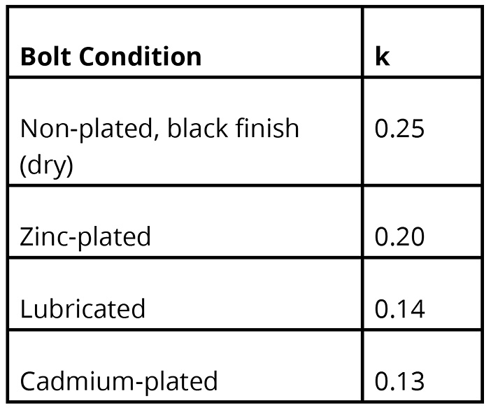
A nut factor of k = 0.2 is commonly used, but the Fastenal Bolted Joint Design paper gives a summary of values for a number of bolt conditions:
K Factors
“Bolted Joint Design” Fastenal

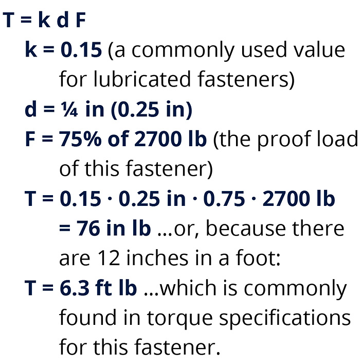
Here is how a recommended torque could be calculated for our ¼-20 Grade 5 bolt:

For reliable clamping forces, it is generally wise to lubricate fasteners before setting their torques.
Mark Doman is a professional engineer with Doman Engineering, a consulting engineering company he established after stints with the State of Michigan, roller coaster manufacturer Arrow Dynamics, and snowmaker SMI.


